
Shear force (SF)
The algebraic sum of unbalanced vertical forces to the left or right side of the section is called shear force. Force applied on per unit area of the member.
Shar force is the force in the beam acting perpendicular to its longitudinal axis.
Bending moment (BM)
The Algebraic sum of moments to the left or right side of the section is called bending moment.
Unit N.m and kN.m
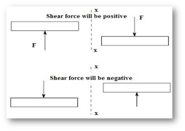
Sign Convention for Shear
- 1. Positive shear force:
- The resultant force normal to the axis of the beam member on the right side of the section which is in the downwards direction and the left side of the section is upwards direction.
- 2. Negative shear force:
- The resultant force normal to the axis of the beam member on the right side of the section which is in a downwards direction and the left side of the section is upwards direction.
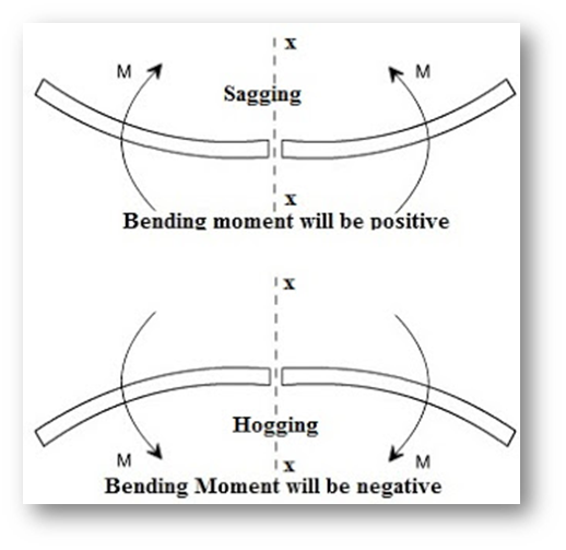
Sign convention for a moment
- 1. Hogging BM:
- The tendency of the BM at the section when the beam bends so as to produce convexity above the centerline. The sign considers as negative. It results that the bottom face of the beam in compression and the top face in tension.
- 2. Sagging BM:
- The tendency of the BM at the section when the beam bends so as to produce concavity above the centerline. The sign considers as positive. It results that the bottom face of the beam in tension and the top face in compression.
Difference between shear force and bending moments
| Shear Diagram | Moment Diagram |
1. Point loads cause a vertical jump in the shear diagram. The direction of the jump is the same as the sign of the point load. 2. Udl result in a straight, sloped line on the shear diagram. 3. The shear diagram is horizontal for distances along the beam with no applied load. 4. The shear at any point along the beam is equal to the slope of the moment at that same point: V = dm/dx | 1. The moment diagram is a straight, sloped line for distances along the beam with no applied load. The slope of the line is equal to the value of the shear 2. Udl results in a parabolic curve on the moment diagram. 3. The max/min values of moment occur where the shear line crosses zero. 4. The moment at any point along the beam is equal to the area under the shear diagram up to that point: M = V dx |
SFD and BMD
It is clear from the discussions that at a section taken on a loaded beam, two internal forces can be visualized, namely, the bending moment and the shear force.
It is also understood that the magnitude of bending moment and shear force varies at different cross-sections over the beam. The diagram depicting the variation of bending moment and shear force over the beam is called bending moment diagram [BMD] and shear force diagram [SFD].
Variation of shear force and bending moment diagrams
| Point load | UDL | UVL | |
| Shear force | Constant | Linear | Parabolic |
| Bending Moment | Linear | Parabolic | Cubic |
Also read: What is structural engineering, What is the scope of structural engineering?
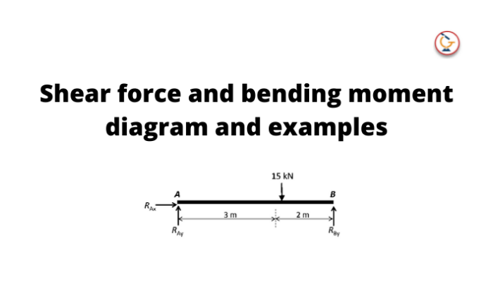
Shear force and bending moment diagram examples:
- Calculate the shear force and bending moment for the beam subjected to a concentrated load, then draw the shear force diagram (SFD) and bending moment diagram (BMD).
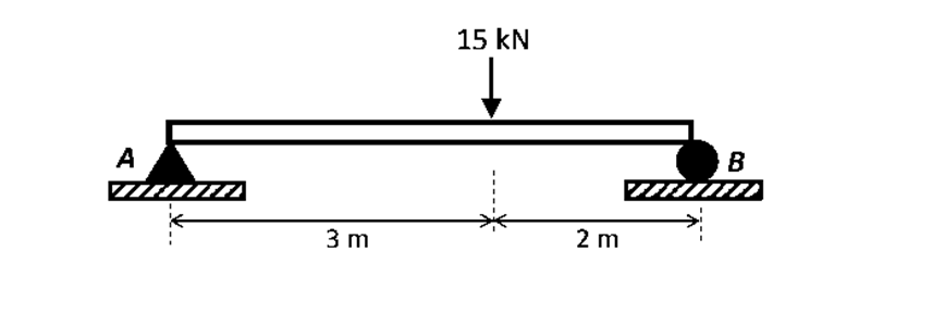
Answer:
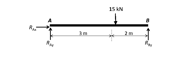
By taking the moment at A,
MA = 0
– RBy × 5 + 15 × 3 = 0
RBy = 9 kN
Fy = 0
RAy + RBy = 15
RAy = 15 – 9
RAy = 6 kN
Fx = 0 ,
RAx = 0
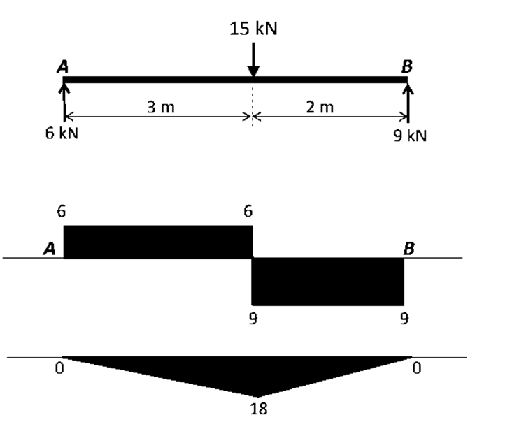
Shear force and bending moment diagram
Get to learn and calculate more examples of the Shear force and bending moment
Learn how you can calculate the values of shear force and bending moment diagram. Get enrolled in the course Basic Structural engineering to learn all basic to advanced structural engineering concepts.


Mayank Panchal is the founder of PIGSO Learning. He has many years of experience in teaching, curriculum development, and instructional designer in civil engineering, Mathematics, and digital marketing space. His passion for conceptual and deep research-based learning helps to understand the subject in depth.